


.jpg)

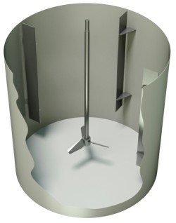
Baffle - tank deflector
| W/T vs. Viscosity Plot | |
| W/T | 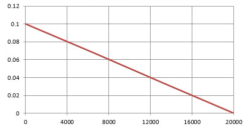 |
| Viscosity (cP) |
Effect of Viscosity on Design
of the deflector
For a high-viscosity mixing fluid, the size of the baffles can be reduced while maintaining effective mixing. The relationship between viscosity and the required baffle width is shown below.
It is important to note that this relationship is only a guideline, as it can result in channels that are too small—with very small distances between the walls—for high-viscosity fluids and small mixing vessels.
Other Considerations
In solid-suspension applications, solids can accumulate in dead zones around the base of the baffles and may be difficult to resuspend. Therefore, in flat-bottom tanks, a gap is left between the base of the baffles and the bottom of the tank.
The latter is generally sized to be identical to the mixing impeller outside the impeller to allow for a small amount of turbulence and ensure that the particles remain in motion and stay suspended at all times.
If it is necessary to convey a low-density or difficult-to-wet powder, leave a gap at the top of the baffles, with the baffles ending below the surface. This, combined with a propeller positioned one to two diameters below the liquid surface, creates a small vortex in the upper part of the tank that rapidly draws the solid material into the main body of the fluid. The gap between the top of the baffle and the fluid surface is generally 300 mm.
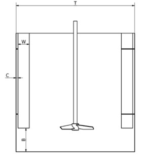 |
T – Inner diameter of the tank |
Thickness of the deflector
The minimum thickness of the deflector can be calculated based on the fluid forces acting on the deflector and the allowable bending stress for the deflector’s construction material. One of the methods presented below assumes that the baffles must absorb the total force provided by the mixer’s torque.
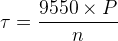 |
τ – Mixer torque (Nm) |
The torque is then converted into a force applied to the deflectors and divided by the number of deflectors. The adjustment factor (Df) is used to account for the distribution of forces along the length of the deflector, but for a conservative design, it can be set to 1, assuming that all the force transmitted by the mixer is concentrated at a single point.
_1.png "Latex formula") |
FB – Force exerted on each deflector (N) Af – Adjustment factor (set to 1 for a conservative design) NB – Number of deflectors T – Tank diameter (mm) Bw – Deflector width (mm) Bc – Deflector on the wall (mm) |
_1.png "Latex formula") |
Bt – Deflector thickness (mm) |
Non-cylindrical tanks
Non-cylindrical mixing tanks are generally rectangular or horizontal tanks. As noted earlier, these tanks generally do not require baffles, unless a high level of agitation is required. These tanks are asymmetrical with respect to the mixer shaft and are therefore self-deflecting for applications where the applied mixer power is less than 165 W/m³.
Rectangular Tanks |
Horizontal tanks |
|
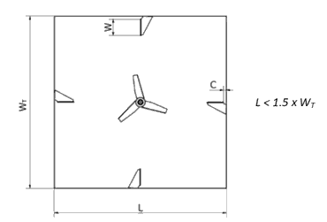
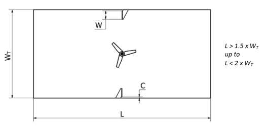
For rectangular tanks, if baffles are required, they can be installed as shown below. The layout is similar to that of a cylindrical tank for tanks that are more or less square. |
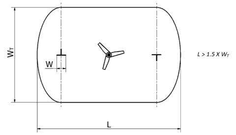
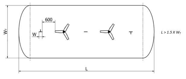
For horizontal tanks, baffles can be mounted as shown below, on the tank’s centerline. Baffles are generally not installed on the curved sides of the tank due to installation difficulties and the need for sufficient clearance from the propeller. |
 |
 |
|
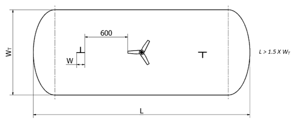
For longer tanks, only the baffles closest to the propeller are necessary, since their effect decreases as one moves away from the mixing propeller. |
For longer tanks, the deflectors are positioned farther from the ends of the tank to provide approximately 600 mm of clearance from the propeller |
 |
 |
|
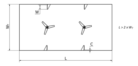
For even longer tanks, it is generally recommended to use multiple mixers. Deflectors should be installed next to each mixer. |
For rectangular tanks, when multiple mixers are used, baffles must be installed for each mixer. The baffles are generally positioned as shown below, with a uniform clearance of 600 mm, and installed along the entire length of the tank. |
 |
 |