


.jpg)




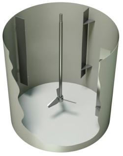
Tank Baffles for Industrial Mixing
| W/T vs. Viscosity Plot | |
| W/T | 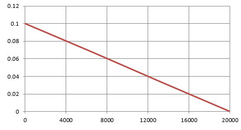 |
| Viscosity (cP) |
Effect of Viscosity on Baffle Design
With more viscous liquids, baffles can be made narrower while still mixing effectively. The relationship between viscosity and the required baffle width is shown in the chart.
This relationship is only a guideline: for very viscous liquids in small vessels, it can give baffles and wall clearances that are too narrow.
Other Considerations
In solids suspension, solids can settle in dead zones at the foot of the baffles and be hard to resuspend. In flat-bottomed tanks, a gap is therefore left between the bottom of the baffles and the tank floor.
This gap is generally sized so that some turbulence from the impeller reaches the tank floor, keeping particles moving and in suspension at all times.
To draw down a light or hard-to-wet powder, the baffles should stop below the liquid surface. Combined with an impeller positioned one to two impeller diameters below the surface, this creates a small vortex in the upper part of the tank that quickly pulls the powder into the liquid. The gap between the top of the baffles and the liquid surface is generally 300 mm.
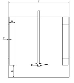 |
T – Inside diameter of the tank |
Baffle Thickness
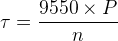
The minimum baffle thickness can be calculated from the fluid forces acting on the baffle and the allowable bending stress of its material. The method below assumes that the baffles must absorb the full force generated by the mixer torque.
 |
τ – Mixer torque (Nm) |
The torque is converted into a force on the baffles and divided by the number of baffles. The adjustment factor (Af) accounts for the distribution of force along the baffle; for a conservative design it can be set to 1, assuming all the force from the mixer acts at a single point.
 |
FB – Force on each baffle (N) Af – Adjustment factor (set to 1 for a conservative design) NB – Number of baffles T – Tank diameter (mm) Bw – Baffle width (mm) Bc – Baffle-to-wall clearance (mm) |
 |
Bt – Baffle thickness (mm) |
Non-cylindrical tanks
Non-cylindrical mixing tanks are usually rectangular or horizontal. As noted above, they generally do not need baffles unless strong agitation is required: being asymmetrical around the mixer shaft, they are self-baffling when the mixer power input is below 165 W/m³.
Rectangular Tanks |
Horizontal tanks |
|
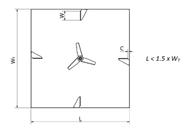
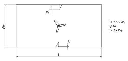
If baffles are required in a rectangular tank, they can be fitted as shown below. For roughly square tanks, the layout is similar to a cylindrical tank. |
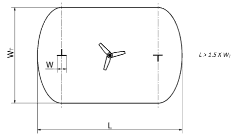
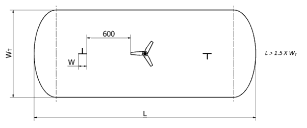
In horizontal tanks, baffles can be mounted on the tank centreline as shown below. They are generally not fitted on the curved sides, because they are hard to install there and need enough clearance from the impeller. |
 |
 |
|
In longer tanks, only the baffles closest to the impeller are needed, as their effect decreases with distance from the impeller. |
In longer tanks, the baffles are set further from the tank ends to leave about 600 mm of clearance from the impeller. |
 |
 |
|
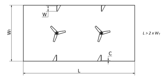
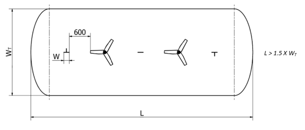
For even longer tanks, several mixers are generally recommended, with baffles next to each mixer. |
When several mixers are used, baffles must be fitted for each mixer. They are generally positioned as shown below, with a uniform 600 mm clearance, along the full length of the tank. |
 |
 |